

INSTRUMENT TRANSFORMER TESTING
Portable instruments for testing CTs, PTs and CVTs
CT and PT Test Equipment
Information Catalogue ![]()
|
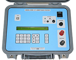
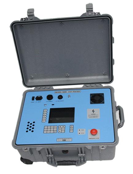
Live CT Tester: MODEL 505B
|
 In
high revenue areas such as universities, shopping malls In
high revenue areas such as universities, shopping mallsand business centres, taking CT's offline for testing is not an option, so a reliable live CT test alternative is required. Live CT testing using admittance... A component of a good CT's characteristic performance is a low admittance value. This admittance value can be measured while in-circuit using the 505B (pictured). The 505B is placed in series with an in-circuit CT and it superimposes a small 1.6kHz signal onto the live 50 or 60Hz secondary metering circuit. A filter on board the 505B extracts the 1.6kHz admittance reading and from this a quick determination is made on the CT's general health. Admittance testing only adds an extra 10 minutes to a polyphase meter test and is quickly becoming part of a routine test requirement for some utilities. The 505B can perform the following measurements: Voltage and current at 50 or 60Hz. 1.6kHz admittance test on a CT secondary. 1.6kHz admittance test on a CT secondary plus the complete metering loop. VA burden of the metering loop downstream from the test block, or at the CT secondary terminals. VA burden of the metering loop from VT secondary terminals or at its test block. A USB interface is also provided on the front panel for downloading results data to a PC. |
CT & PT TESTER: MODEL 590J-V2
|
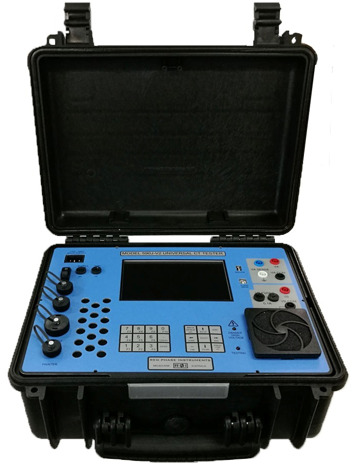 Performing field test measurements of Current and Potential Performing field test measurements of Current and PotentialTransformers has been made far simpler with the Model 590J-V2. This full featured product combines all of the metering CT test abilities of the popular 590G-V2 model with the additional advantage of also being able to perform both protection CT excitation tests as well as burden based inductive PT tests. The 590J-V2 eliminates the need for additional bulky accessories usually required to perform various tests on different types of equipment, saving the operator valuable time and money. Light weight and portable, the 590J-V2 is housed in a ruggedized plastic case and is supplied with the necessary test cables and attachment accessories. It is further packaged in a foam lined transit case for safe transport. It features the following offline test capabilities: - Burden based CT and PT ratio and phase error measurements to an accuracy of 0.02% - Excitation measurements of Protection Class CTs - Optional Live CT test capability with 590F accessory - CT and PT secondary winding resistance, PT primary included - CT 1.6 kHz Admittance test - Simulated Full Load inductive PT testing on up to 2 windings with or without Junction box - CT and PT Burden test - CT and PT polarity check - Batch testing of metering CTs - No name plate CT Class Estimation - Record download to USB Flash or optionally via Bluetooth to an Android tablet or phone. This full featured CT and PT test instrument lowers testing costs by being simple, fool-proof and fast. It's capabilities allow utility personnel and test technicians to pursue the very important task of testing field based instrument transformers for measurement losses, faults or tampering. |
|
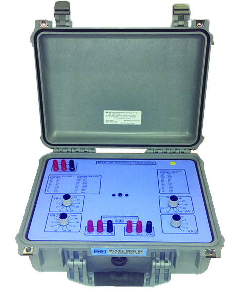
CT TESTER: MODEL 590G-V3
|
Since 1999, Red Phase Instruments has led the way in the manufacture of portable CT error testing equipment. Our portable analysis method has allowed utilities around the world to test their metering CTs easier and faster than using bulky traditional methods without jeopardizing accuracy. Following feedback from our users, our Model 590G-V3 is the latest version of this successful and well proven CT error tester. The 590G-V3 has all the features and advantages of the previous models with additional testing features, better accuracy and smaller size and weight.  In a world where cost control is gaining importance, this CT tester not only lowers testing costs by being simple, fool-proof and fast. It also allows utilities to pursue the very important (yet at many times forgotten) task of testing installed CTs for detecting tampering, and minimizing losses due to faulty CTs. It features the following offline test capabilities: - Burden based CT and PT ratio and phase error measurements to an accuracy of 0.02% - Excitation measurements for most metering Class CTs - CT secondary winding resistance - CT 1.6 kHz Admittance test - CT and PT Burden test - CT and PT polarity check - Batch testing of metering CTs - No name plate CT Class Estimation - Record download to USB Flash or optionally via Bluetooth to an Android tablet or phone. - Remote control via Bluetooth - Multitap, option for a 5 ratio metering CT
|
|
LIVE LV CT TESTER: MODEL 595LV |
 The model 595LV is designed to test the translational integrity of Low Voltage* metering CTs which are permanently commissioned and cannot be taken offline. To determine the translational accuracy of a live CT, the 595LV measures the primary and secondary current over a predetermined number of samples. The current ratio and phase angle errors are calculated for each sample and an average is taken to give the final translational current and phase error accurate to within 0.1% of the CT manufacturer's specification at rated current. To measure the primary current the instrument has provision for two types of current clamps: - a 50mm ID 1000:1 ratio clamp, able to measure primary loads up to 1200 Amps - an 85mm ID 3000:2 ratio clamp, able to measure primary loads up to 3600 Amps The secondary current is measured by the 595LV using one of two methods: - 8 to 20mm ID 1000:1 ratio clamp, able to measure up to 10 Amps - Direct connect to CT terminals, able to measure up to 10 Amps The clamps listed above are electronically compensated for accuracy within the 595LV, so the correct clamp must be selected from the unit's menu before a test is performed. Other features: - Live admittance testing - Colour touch screen - GPS, for accurate sampling and phase synchronization - USB for record transfer to flash stick - Bluetooth for communication with High Voltage clamp accessory, 595HV - Mains and battery powered - Battery capacity is 12 Vdc / 30Wh lithium * - LV or Low Voltage metering installations are typical less than 600 VAC. |
|
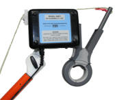
LIVE HV CT TESTER: MODEL 595HV
|
 The model 595HV has been developed to work as an isolated high voltage primary current extension to the 595LV above. The 595HV wirelessly connects to the 595LV and the two synchronously measure and sample a HV CT's current and phase error accurately to within 0.1% of manufacturer's specification. The default clamp size is 32 mm inner diameter and is suitable for most HV feeders. It is a 1000:1 ratio and the opening and closing action is controlled by a servo motor embedded within the instrument's case. Positioning any clamp onto a HV cable can be particularly challenging especially if the hot stick onto which it's mounted is very long. The 595HV has made this easier with an embedded camera which faces the clamp direction. The image is transmitted to a 5 or 6 inch colour display placed in a swivel clamp and positioned at the operator's eye level on the hot stick. This allows the operator to more clearly position the clamp beneath the HV line of interest and then activate the clamp to close around the line. The 595HV may also be used to perform live load testing of high voltage feeders to detect suspicious energy siphoning or branches of excess usage. Other features include: - Infrared control of clamp jaws opening and closing - Bluetooth, for communication with the 595LV - GPS for phase synchronization - Screw mountable; can quickly be mounted onto a hot stick or even a drone with a dedicated platform - Internal battery; 12 Vdc / 30 Wh lithium ion - Weighs approx 2 kg or 4.4 pounds |
|
CVT TESTER: MODEL 590K
|
 True
burden based CVT analysis done portably!! True
burden based CVT analysis done portably!!
Features include: Ability to test for ratio errors at up to 500VA burden. Selectable Power Factor. Ratio error accuracy to 0.05%. Four selectable CVT test point standards to choose from. Tests CVT rated to 500kV with up to 3 secondary windings. Truly portable ~ 20kg. Please note: This is not a simple ratio / nameplate comparison tester. The R & D that has gone into developing this instrument is second to none. Over 60 CVT's from over 12 manufacturers have been carefully characterized under lab and field conditions to create a complex software model that is able to measure a known CVT down to a 0.05% or better ratio error and even an unknown CVT to only a 0.25% error under real load conditions. Under test conditions the 590K takes a number of measurements and characterizes the CVT. It then calculates the performance of the CVT under different loads and applied voltage conditions to suit any of the four common test types used on a CVT. If other test points are required, Red Phase Instruments is able to modify these points to suit any regulation. So when compared to traditional methods the 590K stands out as the only real portable alternative for real load ratio assessment over a wide VA range and flexible Power Factor settings. The CVT tester uses a combination of a Digital Signal Processor and a PC104 mini computer to provide a powerful and yet easy use instrument running on a Windows XP operating system. A large colour display on the front panel presents a large amount of easy to follow information.  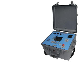 |
|
590 REFERENCE TRANSFORMER MODEL 590J-RT |
 Our 590 reference Transformer is a valuable reference
platform Our 590 reference Transformer is a valuable reference
platformfor the calibration of our 590 series of CT Testers. The reference Transformer comes in a rugged pelican case with with terminal posts for connection and selectable transformer tap switches which allow the operator to calibrate a 590 series CT tester over a wide range of ratio settings. These ratio settings on a 590 series CT test instrument are called gain constants. By selecting the appropriate reference taps on the 590J-RT, the user is able to adjust the gain setting on the 590 CT tester to more accurately reflect the true ratio. |